Autocad Drawing Settings Dialog Box
Snap and Grid Tab (Drafting Settings Dialog Box)
Specifies Snap and Grid settings.
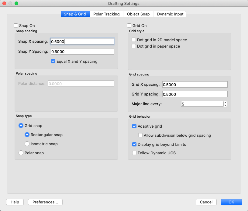
Snap On
Turns Snap mode on or off. You can also turn Snap mode on or off by clicking Snap on the status bar, by pressing F9, or by using the SNAPMODE system variable.
Snap Spacing
Controls an invisible, rectangular grid of snap locations that restricts cursor movement to specified X and Y intervals.
- Snap X Spacing
-
Specifies the snap spacing in the X direction. The value must be a positive real number. (SNAPUNIT system variable)
- Snap Y Spacing
-
Specifies the snap spacing in the Y direction. The value must be a positive real number. (SNAPUNIT system variable)
- Equal X and Y Spacing
-
Forces the X and Y spacing to the same values for snap spacing and for grid spacing. The snap spacing intervals can be different from the grid spacing intervals.
Polar Spacing
Controls the PolarSnap™ increment distance.
- Polar Distance
-
Sets the snap increment distance when PolarSnap is selected under Snap Type & Style. If this value is 0, the PolarSnap distance assumes the value for Snap X Spacing. The Polar Distance setting is used in conjunction with polar tracking and/or object snap tracking. If neither tracking feature is enabled, the Polar Distance setting has no effect. (POLARDIST system variable)
Snap Type
Sets the snap style and snap type.
- Grid Snap
-
Sets the snap type to Grid. When you specify points, the cursor snaps along vertical or horizontal grid points. (SNAPTYPE system variable)
- Rectangular Snap:
-
Sets the snap style to standard Rectangular snap mode. When the snap type is set to Grid snap and Snap mode is on, the cursor snaps to a rectangular snap grid. (SNAPSTYL system variable)
- Isometric Snap
-
Sets the snap style to Isometric snap mode. When the snap type is set to Grid snap and Snap mode is on, the cursor snaps to an isometric snap grid. (SNAPSTYL system variable)
- PolarSnap
-
Sets the snap type to Polar. When Snap mode is on and you specify points with polar tracking turned on, the cursor snaps along polar alignment angles set on the Polar Tracking tab relative to the starting polar tracking point. (SNAPTYPE system variable)
Grid On
Turns the grid on or off. You can also turn grid mode on or off by clicking Grid on the status bar, by pressing Fn-F7, or by using the GRIDMODE system variable.
Grid Style
Sets the grid style in 2D contexts. You can also set grid style by using the GRIDSTYLE system variable.
- Dot Grid in 2D Model Space
-
Sets the grid style to dotted grid for 2D model space. (GRIDSTYLE system variable)
- Dot Grid in Paper Space
-
Sets the grid style to dotted grid for sheet and layout. (GRIDSTYLE system variable)
Grid Spacing
Controls the display of a grid that helps you visualize distances.
Note: The limits of the grid are controlled by the LIMITS command and the GRIDDISPLAY system variable.
- Grid X Spacing
-
Specifies the grid spacing in the X direction. If this value is 0, the grid assumes the value set for Snap X Spacing. (GRIDUNIT system variable)
- Grid Y Spacing
-
Specifies the grid spacing in the Y direction. If this value is 0, the grid assumes the value set for Snap Y Spacing. (GRIDUNIT system variable)
- Major Line Every
-
Specifies the frequency of major grid lines compared to minor grid lines. Grid lines rather than grid dots are displayed when SHADEMODE is set to Hidden. (GRIDMAJOR system variable)
Grid Behavior
Controls the appearance of the grid lines that are displayed when SHADEMODE is set to Hidden.
- Adaptive Grid
-
Limits the density of the grid when zoomed out. (GRIDDISPLAY system variable)
Allow Subdivision Below Grid Spacing:
Generates additional, more closely spaced grid lines when zoomed in. The frequency of these grid lines is determined by the frequency of the major grid lines. (GRIDDISPLAY and GRIDMAJOR system variables)
- Display Grid Beyond Limits
-
Displays the grid beyond the area specified by the LIMITS command. (GRIDDISPLAY system variable)
Polar Tracking Tab (Drafting Settings Dialog Box)
Controls the AutoTrack settings.
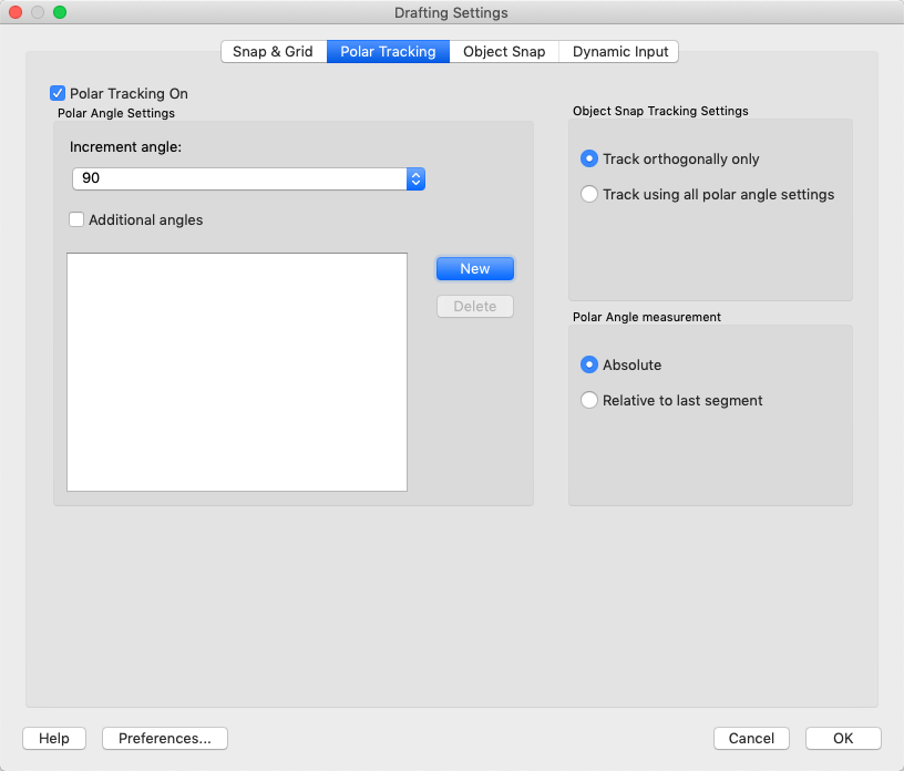
Polar Tracking On
Turns polar tracking on and off. You can also turn polar tracking on or off by pressing F10 or by using the AUTOSNAP system variable.
Polar Angle Settings
Sets the alignment angles for polar tracking. (POLARANG system variable)
- Increment Angle
-
Sets the polar increment angle used to display polar tracking alignment paths. You can select a common angle of 90, 45, 30, 22.5, 18, 15, 10, or 5 degrees from the list. (POLARANG system variable)
- Additional Angles
-
Makes any additional angles in the list available for polar tracking. The Additional Angles check box is also controlled by the POLARMODE system variable, and the list of additional angles is also controlled by the POLARADDANG system variable.
Note: Additional angles are absolute, not incremental.
- List of Angles
-
If Additional Angles is selected, lists the additional angles that are available. To add new angles, click New. To remove existing angles, click Delete. (POLARADDANG system variable)
- New
-
Displays the Add New Angle dialog box. Up to 10 additional polar tracking alignment angles can be added.
Note: Before adding fractional angles, you must set the AUPREC system variable to the appropriate decimal precision to avoid undesired rounding. For example, if the value of AUPREC is 0 (the default value), all fractional angles you enter are rounded to the nearest whole number.
- Delete
-
Deletes selected additional angles.
Object Snap Tracking Settings
Sets options for object snap tracking.
- Track Orthogonally Only
-
Displays only orthogonal (horizontal/vertical) object snap tracking paths for acquired object snap points when object snap tracking is on. (POLARMODE system variable)
- Track Using All Polar Angle Settings
-
Applies polar tracking settings to object snap tracking. When you use object snap tracking, the cursor tracks along polar alignment angles from acquired object snap points. (POLARMODE system variable)
Note: Clicking Polar and Otrack on the status bar also turns polar tracking and object snap tracking on and off.
Polar Angle Measurement
Sets the basis by which polar tracking alignment angles are measured.
- Absolute
-
Bases polar tracking angles on the current user coordinate system (UCS).
- Relative to Last Segment
-
Bases polar tracking angles on the last segment drawn.
Object Snap Tab (Drafting Settings Dialog Box)
Controls running object snap settings. With running object snap settings, also called Osnap, you can specify a snap point at an exact location on an object. When more than one option is selected, the selected snap modes are applied to return a point closest to the center of the aperture box. Press TAB to cycle through the options.
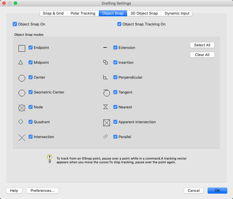
Object Snap On
Turns running object snaps on and off. The object snaps selected under Object Snap Modes are active while object snap is on. (OSMODE system variable)
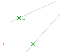
Object Snap Tracking On
Turns object snap tracking on and off. With object snap tracking, the cursor can track along alignment paths based on other object snap points when specifying points in a command. To use object snap tracking, you must turn on one or more object snaps. (AUTOSNAP system variable)
Object Snap Modes
Lists object snaps that you can turn on as running object snaps.
- Endpoint
-
Snaps to the closest endpoint of an arc, elliptical arc, line, polyline segment, spline, region, or ray.
- Midpoint
-
Snaps to the midpoint of an arc, ellipse, elliptical arc, line, polyline segment, region, spline, or xline.
- Center
-
Snaps to the center of an arc, circle, ellipse, or elliptical arc.
- Node
-
Snaps to a point object, dimension definition point, or dimension text origin.
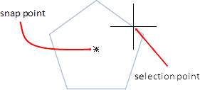
- Geometric Center
-
Snaps to the centroid of any closed polylines and splines.
- Quadrant
-
Snaps to a quadrant point of an arc, circle, ellipse, or elliptical arc.

- Intersection
-
Snaps to the intersection of an arc, circle, ellipse, elliptical arc, line, polyline, ray, region, spline, or xline. Extended Intersection is not available as a running object snap.
Note: You might get varying results if you have both the Intersection and Apparent Intersection running object snaps turned on at the same time.
Intersection and Extended Intersection do not work with edges or corners of 3D solids created in AutoCAD.
- Extension
-
Causes a temporary extension line or arc to be displayed when you pass the cursor over the endpoint of objects, so you can specify points on the extension.
Note: When working in perspective view, you cannot track along the extension line of an arc or elliptical arc.
- Insertion
-
Snaps to the insertion point of an attribute, a block, or text.
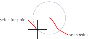
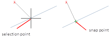
- Perpendicular
-
Snaps to a point perpendicular to an arc, circle, ellipse, elliptical arc, line, polyline, ray, region, 2D solid, spline, or xline.
Deferred Perpendicular snap mode is automatically turned on when the object you are drawing requires that you complete more than one perpendicular snap. You can use a line, arc, circle, polyline, ray, or xline as an object from which to draw a perpendicular line. You can use Deferred Perpendicular to draw perpendicular lines between such objects. When the aperture box passes over a Deferred Perpendicular snap point, an AutoSnap ™ tooltip and marker are displayed.
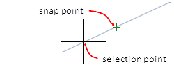
- Tangent
-
Snaps to the tangent of an arc, circle, ellipse, elliptical arc, or spline. Deferred Tangent snap mode is automatically turned on when the object you are drawing requires that you complete more than one tangent snap. You can use Deferred Tangent to draw a line or xline that is tangent to arcs, polyline arcs, or circles. When the aperture box passes over a Deferred Tangent snap point, a marker and an AutoSnap tooltip are displayed.
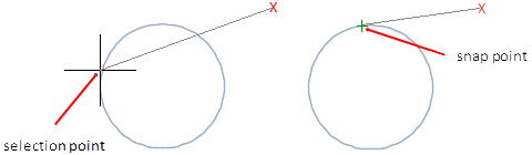
Note: When you use the From option in conjunction with the Tangent snap mode to draw objects other than lines from arcs or circles, the first point drawn is tangent to the arc or circle in relation to the last point selected in the drawing area.
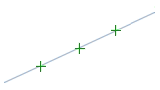
- Nearest
-
Snaps to the nearest point on an arc, circle, ellipse, elliptical arc, line, point, polyline, ray, spline, or xline.
- Apparent Intersection
-
Snaps to the visual intersection of two objects that do not intersect in 3D space but may appear to intersect in the current view.
Extended Apparent Intersection snaps to the imaginary intersection of two objects that would appear to intersect if the objects were extended along their natural paths. Apparent and Extended Apparent Intersection do not work with edges or corners of 3D solids created in AutoCAD.
Note: You might get varying results if you have both the Intersection and Apparent Intersection running object snaps turned on at the same time.
- Parallel
-
Constrains a line segment, polyline segment, ray or xline to be parallel to another linear object. After you specify the first point of a linear object, specify the parallel object snap. Unlike other object snap modes, you move the cursor and hover over another linear object until the angle is acquired. Then, move the cursor back toward the object that you are creating. When the path of the object is parallel to the previous linear object, an alignment path is displayed, which you can use to create the parallel object.
Note: Turn off ORTHO mode before using the parallel object snap. Object snap tracking and polar snap are turned off automatically during a parallel object snap operation. You must specify the first point of a linear object before using the parallel object snap.
- Select All
-
Turns on all object snap modes.
- Clear All
-
Turns off all object snap modes.
Dynamic Input Tab (Drafting Settings Dialog Box)
Controls pointer input, dimension input, dynamic prompting, and the appearance of drafting tooltips.

Enable Pointer Input
Turns on pointer input. When pointer input and dimensional input are both turned on, dimensional input supersedes pointer input when it is available. (DYNMODE system variable)
Pointer Input
Displays the location of the crosshairs as coordinate values in a tooltip near the cursor. When a command prompts you for a point, you can enter coordinate values in the tooltip instead of in the Command window.
- Preview Area
-
Shows an example of pointer input.
- Settings
-
Displays the Pointer Input Settings dialog box.
Enable Dimension Input where Possible
Turns on dimensional input. Dimensional input is not available for some commands that prompt for a second point. (DYNMODE system variable)
Dimension Input
Displays a dimension with tooltips for distance value and angle value when a command prompts you for a second point or a distance. The values in the dimension tooltips change as you move the cursor. You can enter values in the tooltip instead of on the command line.
- Preview Area
-
Shows an example of dimensional input.
- Settings
-
Displays the Dimension Input Settings dialog box.
Dynamic Prompts
Displays prompts in a tooltip near the cursor when necessary in order to complete the command. You can enter values in the tooltip instead of on the command line.
- Preview Area
-
Shows an example of dynamic prompts.
- Show Command Prompting and Command Input near Crosshairs
-
Displays prompts in Dynamic Input tooltips. (DYNPROMPT system variable)
- Show Additional Tips with Command Prompting
-
Controls whether tips for using Shift and Ctrl for grip manipulation are displayed. (DYNINFOTIPS system variable)
Drafting Tooltip Appearance
Displays the Tooltip Appearance dialog box.
crawfordwaskepter.blogspot.com
Source: https://knowledge.autodesk.com/support/autocad-lt-for-mac/learn-explore/caas/CloudHelp/cloudhelp/2022/ENU/AutoCAD-LT-MAC/files/GUID-06D81B23-B171-4F33-920B-4609E22DD9E5-htm.html
0 Response to "Autocad Drawing Settings Dialog Box"
Post a Comment